DaisaTest system

Central battery and control systems

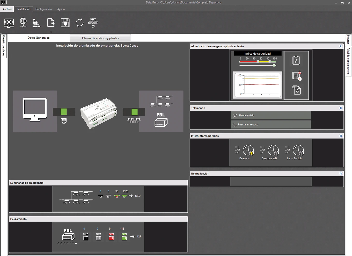
DaisaTest System is a type of emergency lighting facility with capacity to monitor the sta-tus of all luminaires on a control computer and to optimise their maintenance. To achieve this, the DaisaTest System checks that all luminaires are working properly and displays the result of the test in graphic form on signal indicators on the computer monitor or by means of the emergency lighting system Status Reports.

Main functions

Main functions

  • Each luminaire has a specification sheet with information on its battery charge level, spare parts references, duration log, etc.
  • A safety rating can be established on a specific plan or in an area that will indicate the degree of safety in the whole emergency lighting installation.
  • DaisaTest constantly runs checks to verify that the luminaires are supplied with mains power, that communication between the luminaires and the control com-puter is intact, that all batteries are receiving charge and that there are no short circuits in the system.
  • It performs a functional test every 30 days (this can be configured from 3 to 30 days) that verifies the switch-on process of the emergency lamp.
  • It performs a duration test on every luminaire every 3 months (this period can be configured between 3 and 12 months) or after any change of battery due to a du-ration fault.

DaisaTest facilitates maintenance of the facility and controls when, where and how maintenance personnel are to act. It enables definition of the automatic alert e-mail that the user will receive when a situation requiring a maintenance tasks occurs. 

For each plan that requires maintenance, DaisaTest will inform you with a Mainte-nance Proposal, with the aim of optimising the maintenance costs of the emer-gency lighting installation and facilitating the record of the maintenance tasks per-formed.
Additional features

Additional features

  • Specific Alert Levels for each zone can be defined from the control station. Only one luminaire will perform the duration test within the same area at any one time while the rest of the lamps remain available in case there is a mains out-age.
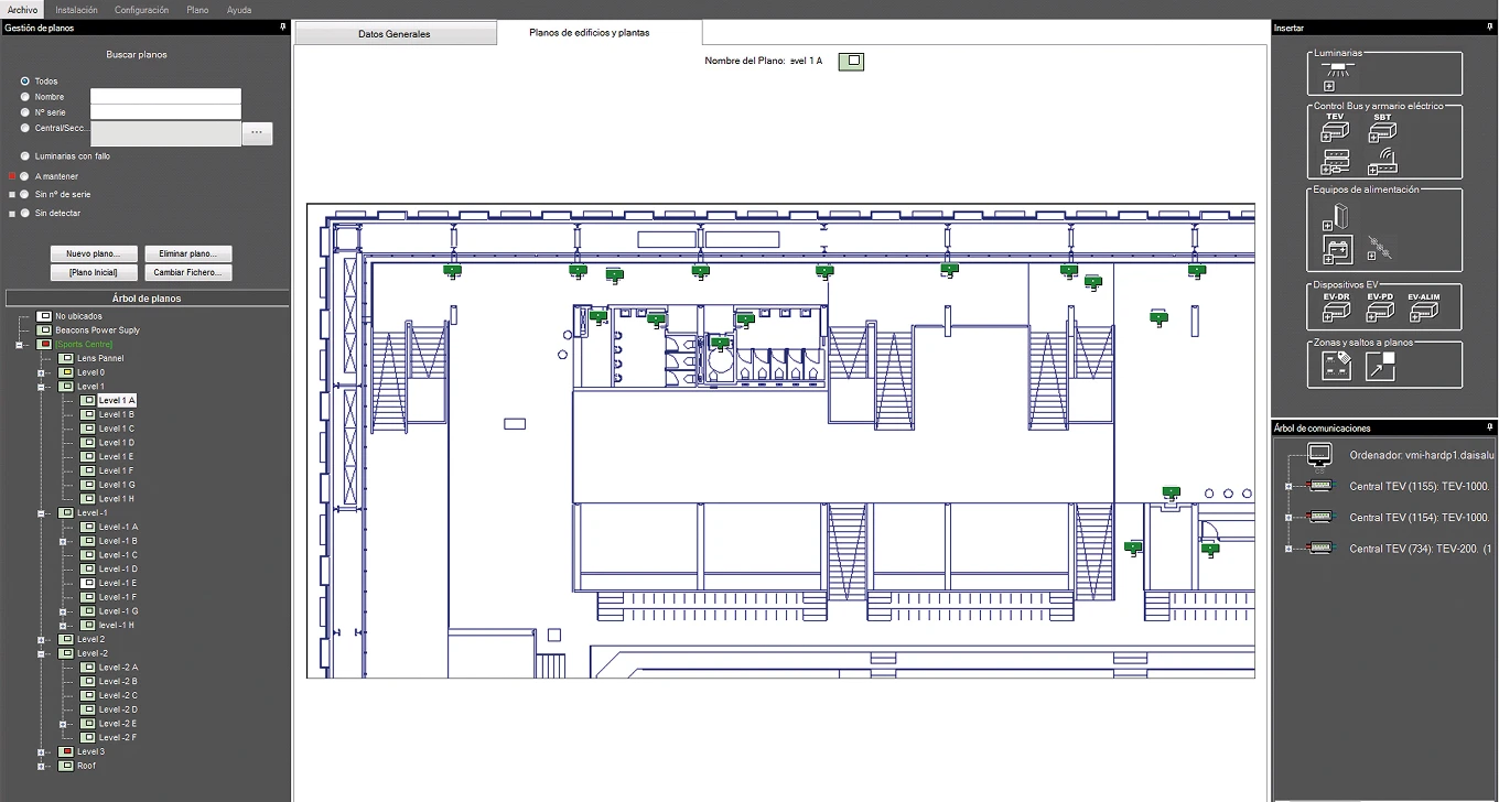
  • DaisaTest enables search of circuits, or luminaires. Thanks to its graphic brows-ing system among the circuits, it facilitates identification of the status of all cir-cuits and provides immediate access.
  • It is possible to turn maintained luminaires and beacon lighting on and off with mains power connected and set up lighting up schedules to save energy in the absence of public.
  • It enables performance of the functional test or programming of the duration test on any luminaire at any time.
  • It manages uninstalling or installing new luminaires and extension to, or chang-es in, the rooms of the building.
  • It works as a conventional remote control (places emergency luminaires in rest mode or turns them on again in the event of mains outage), and enables inhibi-tion mode schedules for areas closed to the public in which emergency lighting is not required.
  • It can send configurable email notifications to different users, including reports on the status of the installation, maintenance needs and proposals, installation insecurities and different alerts.
     
DaisaTest system diagram

DaisaTest system diagram

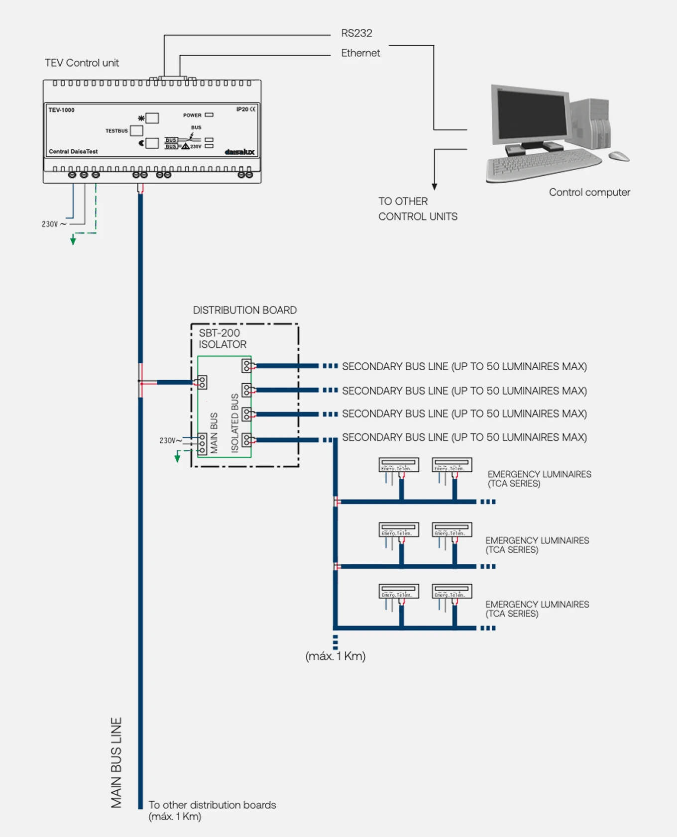
Wiring diagram DaisaTest / TEV-1000, TEV-500, TEV-200

TCA series emergency luminaires

TCA series emergency luminaires

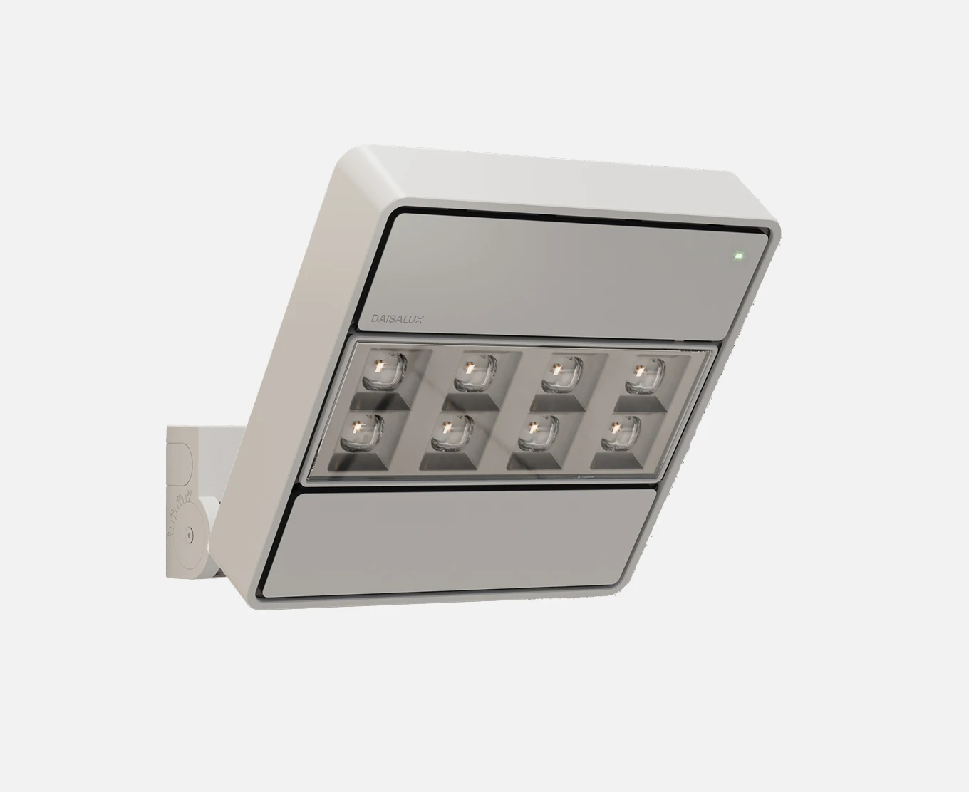
Are capable of communicating with a TEV control unit and of performing functional and duration tests. This TCA series includes all Daisalux emergency luminaires and units. 

Each TCA emergency luminaire detects and notifies its status by means of its LED indicators. Thus, a fault or status can be recognised visually and the appropriate action taken. 

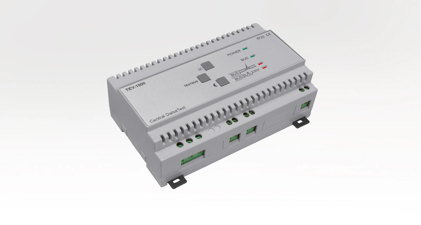
TEV-1000, TEV-500, TEV-200 control units

TEV-1000, TEV-500, TEV-200 control units

Are the communication centres of the DaisaTest System between the luminaires and the control computer. They communicate with the luminaires through the Bus cable, order the functional and duration tests and log the results, which will be transmitted from the TEV control unit to the control computer via RS232 or Ethernet. 

View more